Simply put, a communication network is a set of equipment (routers, servers, switches, etc) and facilities (copper wires, optical fiber) that provide communication services, to transfer information between locations.
Evolution of Communication Networks
In the history, the evolution of services influence the design of network architecture:
- Telegraph networks
- A message is transmitted using signals (drums, beacons, electricity, light, etc).
- 1837, Morse Code converts text message in sequence of dots and dashes.
- Electric Telegraph Networks uses Message Switching and Store-and-Forward operation. The key elements include: Framing, Multiplexing, Addressing, Routing, Forwarding, which are very similar to today’s package networking.
- Telephone networks
- 1876, Bell invented telephone, a service involves two-way, real-time transmission of voice signals across a network.
- 1878, circuit switching (connection oriented) was introduced, only N connections are required to central office (CO) to interconnect N users.
- Hierarchical Network Structure: end-to-end connection across central offices, decimal numbering system.
- Internet, optical, wireless networks
- Packet switching
- Virtual circuit switching
- Next generation Internet
Evolution of Computer Networks
- 1960s: Terminal-oriented networks for sharing a host computer
- Remote access via telephone and modems
- Medium Access Controls for sharing a communication line in arbitrated manner to avoid possible conflicts.
- Messages from a terminal are encapsulated inside a frame.
- Pollling Protocol: central computer sends a poll message to a specific terminal, which will reply a ready information.
- Multiplexing: a multiplexer allows a line to carry frames to / from multiple terminals.
- Error Control Protocols ensure virtually error-free communication.
- 1970s: Computers connected directly to each other
- ARPANET, package switching network
- TCP/IP, Internet protocols
- Ethernet local area network
- 1980s – 2000s: New application and Internet growth
Layers, Services, Protocols
Communication process between machines connected across one or more networks is very complex. Layering partitions related communication functions into manageable groups. Each layer provides a service to the layer above, and each layer operates according to a protocol. Protocol is a set of precise rules that governs:
- How communicating entities in a layer interact.
- What kind of information can be sent and received.
- What kind of actions to take when a certain event occurs.
Layered Architecture and OSI Model
OSI reference model was developed as an open system architecture for the design of computer networks that could communicate with each other. The model partitioned the communication process into seven layers:
| End-to-end communication | Application Layer Presentation Layer Session Layer Transport Layer |
| Network communication | Network Layer Data Link Layer Physical Layer |
The network layer and data link layer involve interaction of peer to peer process across a single hop.
A layering architecture simplifies design, implementation, and testing of networks by partitioning overall communication process into parts. Protocol in each layer can be designed separately from those in other layers. Protocol makes calls for services from the layer below. Layering also provides flexibility for modifying and evolving protocols and services without having to change layers below.
Physical Layer
Physical layer deals with the transmit of bits. It defines and specifies the physical aspects of our communication channel:
- Mechanical: cable, plugs, pins, etc.
- Electrical or optical: modulation, signal strength, voltage levels, bit times, etc.
- Functional or procedural: how to activate, maintain, deactivate physical links, etc.
Examples include Ethernet, DSL, cable modem, telephone modem, twisted-pair cable, coaxial cable, optical fiber, radio, etc.
Data Link Layer
Data link layer provides for the transfer of block of information called the frames across our transmission link that directly connects to nodes. It:
- groups bits into frames
- detects bit errors
- re-transmits frames
- activates, maintains data link connections
- controls the broadcast medium access for Local Area Network
- offers node-to-node flow control to avoid buffer overflow at the receiving node
Network Layer
Network layer provides for the transfer of packets across a communication network or multiple networks. Addressing must be scalable to accommodate a very large number of network users. Networking software jointly execute routing algorithms to determine the routing paths across the network.
Routing protocols mean the procedure used to select routing paths. This function makes network layer as the most complex in the reference model. The network layer is also responsible for congestion control to deal with temporary surges in packet traffic from time to time.
When two hosts are connected at two different networks, transfer of data must traverse two or more networks that are possibly differ in their internal routing and address scheme. Inter-networking is part of network layer and provides transfer of packets, between gateway routers, across multiple and possibly dissimilar networks.
Transport Layer
Transport layer is responsible for the end to end transfer of message segments from the process in a source machine to a process In the destination machine. This layer
- sets up, maintain and release connections
- accepts messages from the higher layer
- prepares segments (or data grams) for transfer between end machines.
Transport Layer provides different kinds of services:
- Reliable stream transfer, or
- Quick-and-simple single block transfer.
Session Layer, Presentation Layer, Application Layer
In practice, Session Layer and Presentation Layer are incorporated into the Application Layer. Application layer is to provide services that are frequently required by applications that involve communication. For example: HTTP protocol, Domain name service, file transfer, email, etc.
OSI View of Layers,Services, Protocols
The OSI reference model contributed to the development of a unified view of layers, protocols, and services.
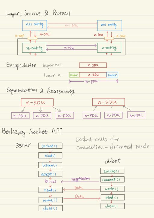
A layer is a set of related communication functions that can be managed and grouped together. Layer n in one machine interacts with layer n in another machine to provide a service to its upper layer n+1. The entities comprising the corresponding layer on different machines are called peer processes. The processes at layer n are referred to as layer n entities.
The machines at the same layer use a set of precise rules called as a layer-n protocol. Layer-n peer processes communicate by exchanging protocol data units (PDUs). Communication between peer processes is virtual and actually indirect. Layer n+1 transfer the information by invoking the services provided by layer n. Services are available at service access points (SAPs). Each layer passes data and control information to the layer below it, until the Physical Layer is reached and transfer occurs.
Data passed to the layer below is called Service Data Units (SDUs), which are encapsulated in PDUs. A header and sometimes, a trailer are appended. This process is called encapsulation. The header often carries information such as addresses, sequance number, flag bits, length, etc. Trailer may contain the check bits, say, CRC for error control.
In the layering architecture, each layer adds a header and possibly a CRC checksum trailer to the block of the information. At the destination, each layer reaches its corresponding header to determine what actions to take and it eventually pass the block of information to the layer above after removing the header and the trailer. Bandwidth utilization is calculated as the ratio between application data and all data transferred:
Utilization = App Data / (App Data + Headers + CRC)A layer may impose a limit on the size of data blocks that it can transfer. A N+1 layer SDU may be too long to be handled as a single unit by lower N layer. At the sender side, SDU is segmented into multiple PDUs. At the receiver side, SDU is reassembled from sequence of PDUs.
A connection-oriented service has three phase: connection set up, SDU transfer, and a connection release. A connection-less service doesn’t require connection set up and as each SDU is transmitted directly.
Inter-networking is to build a network of networks or Internet. It can
- operate over multiple, coexisting, different network technologies,
- provide ubiquitous connectivity through the IP packet transfer,
- achieve huge economic of scale while provisioning universal communication service.
What glues Internet together is Internet Protocol (IP). IP packets transfer information across the Internet. IP layer in each router determines next router. Network interface transfer IP packets across networks.
TCP/IP: Architecture and Routing
| Application Layer | HTTP, SMTP, DNS, RTP, etc. |
| Transport Layer | TCP: Reliable stream service UDP: Best-effort user datagram service |
| Network Layer | IP: Best-effort connection-less package transfer ICMP, ARP, etc. |
| Data Link & Physical Layer | Network interfaces |
All higher-layer protocols access a network interface through IP, which handles the transfer of information across multiple networks through the use of routers. IP provides a single service, best-effort connection-less packet transfer. It provides no mechanism for error recovery or flow control.
Each host on the Internet is identified by a globally unique IP address which identifies the host’s internet interface, rather than the host itself. A router is attached to two or more physical networks, with each network interface is assigned to a unique IP address. For scalability, Internet addresses are hierarchical, i.e. IP Address = Network ID + Host ID. IP packets are routed according to Network ID. Routers compute the routing tables using distributed algorithms.
A network interface is identified by a globally unique physical address MAC. The network uses its own address to transfer packets (or frames) to the appropriate destination. So, the IP address needs to be resolved to a physical address at each IP network interface, by Address Resolution Protocol (ARP).
Berkeley Socket API
An API allows application programs to access certain resources through a predefined interface. The most popular APIs that provide access to network resources is Berkeley Socket API, which hides the details of underlying communication technologies as much as possible. Programmers do not have to worry about networking details. Another popular socket is WinSock in Microsoft Windows.
In a typical scenario, one application operates as a server, while the other as a client. Sockets are in kernel space, their interfaces (accessible by descriptors) are in user space.
Host computers run two transport protocols on top of IP to enable process-to-process communications: TCP and UDP.
| TCP | Connection-oriented reliable transfer of a stream of bytes. 1. An application sets up connection between peer processes. 2. Reliable bidirectional in-sequence transfer of byte stream. (Message boundaries are not preserved in transfer.) 3. Multiple read and write between peer processes. 4. Connection is released. |
| UDP | Best-effort connection-less transfer of individual block of information. 1. No connection setup, a block of information is transferred immediately. (Message boundaries are preserved.) 2. No setup overhead & delay. 3. Destination address with each block. 4. Send to / receive from multiple peer processes. 5. Best-effort service only. (Messages may be out of order when received, or lost.) |
There are some key differences in programming server and this client.
| Server | 1. Specify well-known port number when creating socket. 2. May have multiple IP addresses (network interfaces). 3. Waits passively for client requests. |
| Client | 1. Assigned ephemeral port number. 2. Initiates communication with server. 3. Needs to know server’s IP address and port number. 4. Consults DNS service for translation between domain name and IP address. |
Socket Calls for Connection-Oriented Mode
Server begins by carrying out a Passive Open.
| socket() | 1. Creates a socket to listen for connection requests. 2. It returns a socket descriptor (an integer number) if success. |
| bind() | 1. Binds local IP address and well-known port number to socket descriptor. 2. It can wildcard IP addresses for multiple network interfaces. |
| listen() | 1. Turns a socket into a listening socket, that can accept incoming connection from clients. 2. Specify the maximum number of requests which may be queued while waiting for server to accept them. |
| accept() | 1. Accepts incoming requests, it blocks if queue is empty. 2. When the TCP connection is established, this function wakes up and returns a new socket descriptor for the given connection. 3. Client and server use new socket for data transfer, while the original socket continues to listen for new requests from a client. |
Client does Active Open:
| socket() | Creates a socket to connect to the server(). |
| connect() | Establishes a connection on the local socket with the specified descriptor to the remote address and port number. This indeed initiates a three-way handshaking process for connection buildup. |
For data transfer, client or server calls:
| write() | 1. Transmits data into the connected socket. 2. It returns the number of bytes transferred, if success. 3. It blocks until all data is transferred. |
| read() | 1. Receive data from the connected socket. 2. It returns the number of bytes read, if success. 3. it blocks if no data arrived. |
| close() | 1. Closes out the TCP connection. |
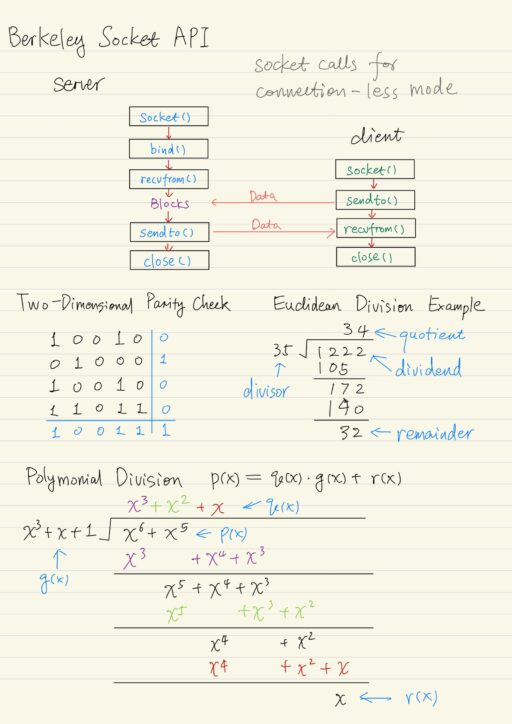
Socket Calls for Connection-Less Mode
Server starts first.
| socket() | 1. Creates a socket of type UDP. 2. It returns a socket descriptor (an integer number) if success. |
| bind() | 1. Binds local IP address and well-known port number to socket descriptor. |
Client started then.
| socket() | 1. Creates a socket of type UDP. 2. It returns a socket descriptor (an integer number) if success. |
For data transfer, client or server calls:
| recvfrom() | 1. Receive data from the socket. 2. It blocks until the data arrives. 3. It returns the number of bytes received. |
| sendto() | 1. Transfer data to the socket. |
| close() | 1. Socket is no longer needed. |
UDP is unreliable, programmer has to:
- take care of reliability assurance by themselves
- use timeout mechanism to avoid waiting forever
- re-transmit a message if it is lost.
- reorder and de-duplicate messages if necessary.
Digital Transmission
Information can be grouped into two broad categories:
| Block | Information that occurs in a single block. E.g. text message, data file, JPEG image. |
| Stream | Information that is produced and transmitted continuously. E.g. real-time voice, streaming video. |
The delay of communication between two nodes has two components:
| Propagation delay | tprop = d / vwhere, tprop is time for signal to propagate across medium,d is the distance between two nodes in meters,v is the speed of light in the transmission medium (3 * 108 m/s) |
| Transmission delay | ttrans = L / Rwhere, L is the number of bits in messagesR is the bandwidth of digital transmission system (unit: bits per second) |
Overall Delay = tprop + ttrans = d / v + L / RWe could:
- use data compression to reduce L.
- Noiseless: original information recovered exactly. E.g. zip, compress, GIF, fax.
- Noisy: recover information approximately. E.g. JPEG.
- use higher bandwidth to increase R.
- place nodes closer to each other to reduce d.
There are two ways of transmission of stream information:
| Constant bit-rate | Signals such as digitized telephone voice at 64kbps. Network must support steady transfer of signals. |
| Variable bit-rate | Signals such as digitized video that varies in bit-rate according to motion and detail in a scene. Network must support variable transfer rate of signal. |
For transmission to occur, there must be transmission medium that conveys energy of a signal from a transmitter to a receiver.
| Transmitter | Converts information into signal suitable for transimission. Injects energy into communication medium or channel. E.g. telephone converts voice into electric current, modem converts bits into tones. |
| Receiver | Receives energy from medium. Converts received signals into the form suitable for delivery to user. |
If there are network transmission impairments, such as signal attenuation, distortion, or interference, then stream Quality-of-Service issue arise, such as delay, jitter, loss. Application and Application Layer protocols are developed to deal with these impairments. For long distance communication, re-generators (repeaters) are used to recover original data sequence and re-transmit on the next transmission segment. Different digital transmission systems have various bit rates, costs, bit-error-rates and usages.
Error Control
Digital transmission systems introduce errors with different per bit error probability. Error control is used when transmission system doesn’t meet the application’s requirements, to ensure that a data stream is transmitted to a certain level of accuracy.
There are two basic approaches to error control:
- Error detection and re-transmission.
- Error correction (without re-transmission).
Error Detection
One important term is called codeword. A n-bit codeword is a frame of m-bit data plus k-bit redundant check bits, such that n = m + k. The basic idea of error detection is simple. All transmitted data blocks “codewords” satisfy a specific pattern. The receiver checks the codeword coming out of the channel, to see whether the pattern is satisfied. If it is not, the receiver can be certain that an error has occurred.
Single Parity Check
The simplest code is the Single Parity Check code. It takes k information bits and appends a single check bit to form a codeword.
data bits: b1, b2, b3, ..., bk
check bit: bk+1 = b1 + ... + bk modulo 2
codeword:  (b1, b2, ..., bk, bk+1)
The parity check bit is calculated by modulo 2 arithmetic. The parity check bit ensures that the total numbers of 1s in the codeword is even, that is, the codeword has even parity.
Receiver checks to see if the number of 1s is even in the codeword. However, this method has a problem that the error of even number of bits are undetectable.
Many transmission channels introduce bit errors at random. Let p be the probability of an error in a single bit transmission. The probability of a bit without error in transmission is 1- p. So in a n-bit codeword, the probability of 1-bit error is
P[1-bit error] = (n1)p(1-p)n-1The probability of j-bit errors is:
P[j-bit errors] = (nj)pj(1-p)n-jSome error patterns are more probable than others, for example:
P[10000000] = p(1-p)7 = (1-p)8 (p/(1-p))1
P[11000000] = p2(1-p)6 = (1-p)8 (p/(1-p))2
with p < 0.5, so p/(1-p) < 1
It follows that patterns with 1 error are more likely than patterns with 2 errors.
The undetectable error by single parity check occurs if there are even number of bit errors. The probability of the undetectable error pattern is:
P[undetectable] = (n2)p2(1-p)n-2 + (n4)p4(1-p)n-4 + ...When n = 32, and p = 0.001, roughly 1 in 2000 error patterns is undetectable by single parity. It is possible to detect more errors if we add more check bits.
Two-Dimensional Parity Check
A simple method to improving the error detection capability of single parity check, is to arrange data in a k-by-k matrix, then:
- Add (k+1) column, which consists of check bits for each row.
- Add (k+1) row, which consists of check bits for each column.
The result encoded a k+1 by k+1 matrix of bits satisfies the pattern that all rows have even parity and all columns have even parity. Two-dimensional was able to detect 1, 2 and 3 bit errors, but it’s overhead is high. It was used in old systems.
Polynomial Codes
Polynomial codes are used extensively in error detection. It applies polynomial arithmetic instead of parity check sums. Polynomial codes are implemented in shift-register circuits, involving the generation of check bits in the form of a Cyclic Redundancy Check (CRC). Polynomial codes are widely used error control codes, both for error detection and error correction.
In polynomial codes, the information, the codeword and the error vectors are all represented by polynomials with binary coefficients (0 and 1).
(ik-1, ik-2, ..., i1, i0) → ik-1xk-1 + ik-2xk-2 + ... + i1x + i0The binary polynomial arithmetic is done by per bit XOR. Coefficient 2 will be equal to 0, since 1 + 1 = 2 = 0 mod 2. For example:
Addition:
(x7 + x6 + 1) + (x6 + x5)
= x7 + x6 + x6 + x5 + 1
= x7 + (1 + 1)x6 + x5 + 1
= x7 + x5 + 1

Multiplication:
(x + 1) (x2 + x + 1)
= x3 + x2 + x + x2 + x + 1
= x3 + 1
When it comes to the Binary Polynomial Division, we divide our polynomial p(x) by g(x), and we want to get a quotient q(x) and a remainder r(x), such that:
p(x) = q(x) g(x) + r(x)This binary polynomial division can be down similar to the Euclidean Division with decimal number. If the highest power of the interim remainder polynomial is equal or greater than the highest power of the divisor, a new quotient term is computed along with a new interim remainder polynomial. The division process stops when the degree of the remainder is less than the degree of divisor.
Cyclic Redundancy Check (CRC)
Cyclic redundancy check (CRC) uses a polynomial code, which is based on treating bit strings as a presentation of polynomials with coefficient of 0 and 1 only. A k-bit frame is regarded as a coefficient list for a polynomial with k terms, ranging from xk-1 to x0. Such a polynomial is said to be degree k-1. Also note that polynomial arithmetic is done by per-bit XOR operation.
We assume the codeword has n bits, of which k bits are data, n – k bits are check bits. The procedure of error detection is as follow:
- Sender and receiver agree upon a generator polynomial
g(x)in advance, that has a degree n – k. - The k bits data, i.e. information polynomial
i(x)with degree k – 1, is used to calculate the n – k check bits, using generator polynomial g(x) that has a degree of n – k. - The k bits data and n – k check bits are sent into the communication channel.
- On the other side, the received k bits data is used to calculate check bits, which is compared to the received n – k check bits.
- If both of check bits match, the information is accepted.
CRC Encoding Procedure
Given a generator polynomial g(x) that has degree n – k:
g(x) = xn-k + gn-k-1xn-k-1 + ... + g2x2 + g1x + 1
assuming gn-k = 1
and an information polynomial i(x) that has k bits (degree k – 1)
i(x) = ik-1xk-1 + ik-2xk-2 + ... + i2x2 + i1x + i0The CRC encoding procedure is as follows:
- Multiply
i(x)byxn-k. (Done by putting n – k zeros in the lower order positions). - Divide
i(x) xn-kbyg(x)and get a remainder polynomialr(x)of at most degree n – k – 1. This remainder is the CRC check bits. - Add remainder
r(x)toi(x) xn-k. (Done by putting check bits in the n – k lower order positions).
The resulted polynomial will be the transmitted codeword:
b(x) = i(x) xn-k + r(x)CRC Capability
Imagine that a transmission error vector e(x) occurs, e(x) has 1s in error locations and 0s elsewhere. Adding bit by bit to the codeword b(x) by using modulo 2 arithmetic, the sender transmitted b(x), but the receiver receives b(x) + e(x), let us name it R(x).
Receiver divides the R(x) by g(x). The remainder will be the same, if e(x) is a multiple of g(x), then the error will not be detected. So we should select a generator polynomial g(x) such that error patterns e(x) are not multiple of g(x).
- Single error in location
imeanse(x) = xi, ifg(x)has more than 1 term, then it can not dividee(x), the error will be detected. - Double error in location
iandjmeanse(x) = xj + xi = xi (xj-i + 1), again ifg(x)has more than 1 term, it can not dividexi. Further ifg(x)is a primitive polynomial, it can not divide xm+1 for all m < 2n-k – 1. (Need to keep codeword length < 2n-k – 1)
The primitive polynomial can be found by consulting coding theory books. Designing good polynomial codes for more than 2 bit errors is much more sophisticated.
Standard CRC Generator Polynomials
| CRC-8 ATM | x8 + x2 + x + 1 |
| CRC-16 Bisync | x16 + x15 + x2 + 1 = (x + 1) (x15 + x + 1) |
| CCITT-16 HDLC, XMODEM, V.41 | x16 + x12 + x5 + 1 |
| CCITT-32 IEEE 802, DoD, V.42 | x32 + x26 + x23 + x22 + x16 + x12 + x11 + x10 + x8 + x7 + x5 + x4 + x2 + x + 1 |
Internet Checksum
Internet protocols including IP, TCP, UDP use check bits to detect errors, instead of using CRC polynomial. The rationale is the simplicity. Because the checksum must be recalculated at every router, the algorithm for the checksum was selected for its ease of implementation, instead of the strength of error detection capability.
IP header consists of a certain number L of 16-bit words, i.e. b0, b1, ..., bL-1. The 16-bit checksum bL is appended to the header, which is calculated as below:
- Each 16-bit word is treated as integer, find
x = (b0 + b1 + ... + bL-1) modulo 216-1. - The checksum is
bL = -x, which is carried out using 1’s complement arithmetic. - Thus the header must satisfy the following pattern:
0 = (b0 + b1 + ... + bL-1 + bL) modulo 216-1, otherwise there is an error.
My Certificate
For more on Fundamentals of Network Communication, please refer to the wonderful course here https://www.coursera.org/learn/fundamentals-network-communications/
I am Kesler Zhu, thank you for visiting my website. Check out more course reviews at https://KZHU.ai